
The first term you need
to
learn is 'incidence'. The incidence is the angle of the wing relative
to
the model. For our models, it is convenient to reference the incidence
to the body of the model. The wing can be mounted with either zero,
positive,
or negative incidence as illustrated as below.
These same terms can be
used
for the stabilizer as well, and when combined with the wing can result
in several types of what I call 'trim types'. Here is how they can be
combined
and the combinations which do and do not work.
Of the combinations which do work, you will most likely find that the lower three are the ones which you will end up with. The zero-zero combination requires special trimming and a balance point which is much further aft than the what is called out on the plan. You can pick up some duration flying close to a 'zero-zero' setting, however there are some tradeoffs to consider such as reduced stability which may be detrimental to your flying efforts.
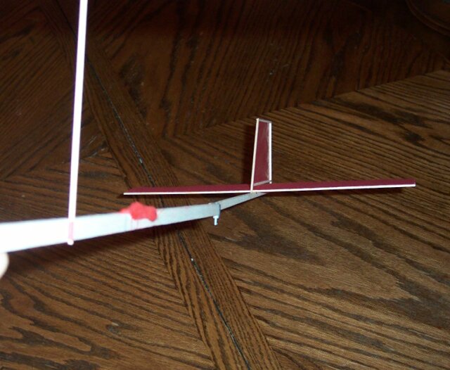
Since we built our model with the boom angled upwards, the tail has negative incidence. Additionally the designs have been optimized for maximum duration and the model is designed to have a very little or no incidence in the wing. Most likely you will fly zero wing incidence for both the B and C models or maybe with 1/16" positive wing incidence. In essence it is the 'zero-neg' trim.
When you fly your model
for
the first time you will want to watch out for certain things.
Stalling is when the
model
pitches up and down over and over again as it flies (see the drawing
above).
Stalling can be cause by several things but the reason it happens is
that
the lift forces from the wing and the tail are not in balance. Like a
see-saw,
the model rotates as the forces try to find a point of equilibrium. The
figure below shows a greatly simplified version of how the forces are
trying
to balance each other.
Lw = lift generated by
the
wing
Lt = lift generated by the
tail
lw = distance from the
balance
(pivot) point to the lift force of the wing
lt = distance from the
balance
(pivot) point to the lift force of the tail
For stable flight the moment (lift force times the distance) of the wing must equal the moment (lift force times the distance) of the tail.
This can be expressed mathematically as: (Lw * lw) = (Lt * lt)
if (Lw * lw) is greater
than
(Lt * lt) then the nose of the model will pitch upwards.
if (Lw * lw) is lower than
(Lt *lt) then the nose of the model will pitch downwards.
So a stalling model is an indication that the nose up forces are winning the see-saw balance. So to counteract that, we have several options.
Your model should have a little bit of left tilt in the tail. If not then it needs to be corrected. A quick and easy method, which may seem extreme, is to grab the boom about 2" behind the rear hook with your left thumb and forefinger, and then grab the boom about 1" further back with your right thumb and forefinger. Then twist your hands in opposite directions from each other making sure that the hand closest to the tail is twisting the direction you want to tail to go. Be gentle when doing this, or you may over twist the boom and crack the wood. If you do not wish to use this method (I use it all of the time though) then you will need to remove the boom from the body and reglue it. Be careful no to overdo the tail tilt otherwise it can cause other flight problems. You should have a few degrees of tail tilt as shown in the diagram above next to "LEFT TILT".
Turning problems can
also
be cause by insufficient left thrust or left rudder. Check to see if
the
model has one (1) to three (3) degrees of left thrust as well as the
1/8"
of boom/rudder offset which was built into it.
Other trim problems can come into play at other parts of the flight. A typical flight can be broken down into three segments. The first is the climb phase which is when the model climbs to the ceiling. Then as the rubber band winds down, then you enter the cruise phase which is when the model flies at about the same altitude for several laps. Finally there is the descent, which is when the model starts coming down from the ceiling and eventually lands on the floor.
Sometimes problems occur in one segment and not in the other which can be quite troublesome to try and figure out. A model may not circle at launch but then circles fine 20 seconds later, or it may try to dive at launch but then flies just fine moments later. Here are some frequent segment specific problems which may arise.
Model flies straight during launch:
The B and C designs for 2003-2004 are a more competitive design than the original version of the Olympus. The B model, with is large stabilizer flies more like a tandem wing aircraft and that kind of model needs some special adjustments. The most important features are the balance point and the upward 'kick' of the tail boom. The aft CG, 2 3/8" behind the wing, allows the tail to provide a large amount of lift and work harder. The upwards kick of the boom helps the model in the cruise portion of the flight and the descent. When you model is starting to come down slowly, you should notice that the tail boom is flying about level to the ground, and the rest of the airplane is actually pointed upwards about 3-5 degrees. This allows the wing to operate at a high angle of attack when it is coming down to help provide maximum lift to increase your flight time. If you find the B model wants to dive only during the launch portion of the flight or when wound with lots of turns, it is probably from not having enough up kick in the boom. The long tail arm and large stab area can overpower the wing under high torque and make it dive or fly fast level laps when first launched. If this is the case, and your CG is correct, then add more up kick in the boom to fix the problem. Ideally you will have zero incidence in the wing and the 7/8" kick in the boom.
The
C
division model also has a large stabilizer, and a CG 3/8" behind the
wing.
The C model wings are much bigger than before and have lots more area,
so we can make them fly well on the big wing they have. To make a C
model
with a giant tail like the B model has, would mean the C model would
have
to be about 40" long and that would be very weak and hard to trim. The
large prop on the C model is the key to its duration potential. The
smaller
tail required less up kick in the boom, but 5/8" should be present to
maximize
the models cruise performance and descent performance. Both the B and C
models feature a large amount of wing offset. If you measure them, you
will see the left side of the wing is a fair bit larger than the right
side of the wing. The stab on each model is also built with offset, the
left side is longer than the right. What this does is to provide more
lift
on the left side of the model to counteract the torque of the
propellor.
the propellors are bigger this year and the rubber size is bigger as
well,
so more torque is present. The offset wing and stab, plus the washin
built
into the wing should be more than enough to compensate for the extra
torque.