Ideally
your model will fly correctly right from the start. However, sometimes
they do not. What your model should do is fly in left had circles about
20 feet in diameter with the nose slightly upwards during the entire
flight
(see photo below).
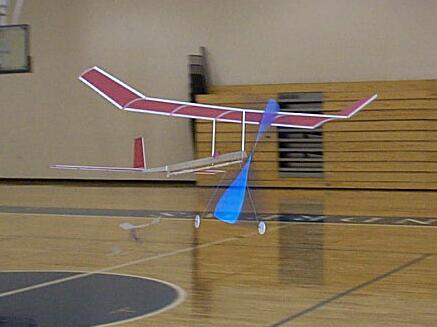
Flight trimming your model
is a very important part of the whole process. A poorly trimmed model
will
suffer in performance and can cause frustration to the person flying
it.
Trimming a model is actually quite easy to do, and once you understand
it a little you will master it in no time.
The first term you need
to
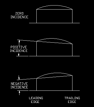
learn is 'incidence'. The incidence is the angle of the wing relative
to
the model. For our models, it is convenient to reference the incidence
to the body of the model. The wing can be mounted with either zero,
positive,
or negative incidence as illustrated as below.
These same terms can be
used
for the stabilizer as well, and when combined with the wing can result
in several types of what I call 'trim types'. Here is how they can be
combined
and the combinations which do and do not work.
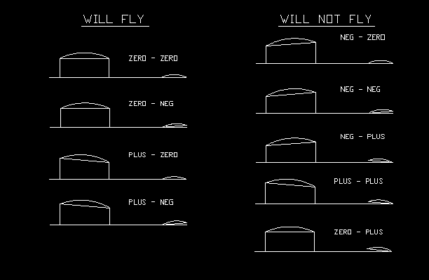
Of the combinations
which
do work, you will most likely find that the lower three are the ones
which
you will end up with. The zero-zero combination requires special
trimming
and a balance point which is much further aft than the .7" called out
on
the plan. You can pick up some duration flying close to a 'zero-zero'
setting,
however there are some tradeoffs to consider such as reduced stability
which may be detrimental to your flying efforts. I will discuss the
'zero-zero'
trim method later.
Since we built our
model
with the body and boom in a straight line, the tail has zero incidence.
Because we balanced the model at .7" in front of the trailing edge of
the
wing, it will be necessary to add some positive incidence to the wing
to
properly trim the model. This is done by raising the the leading edge
wingpost
1/8 of an inch higher than the rear wing post. This is the plus - zero
trim setting.
When you fly your model
for
the first time you will want to watch out for certain things.
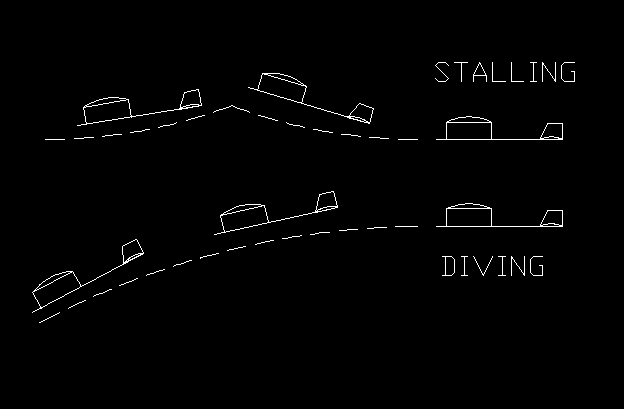
Stalling is when the
model
pitches up and down over and over again as it flies (see the drawing
above).
Stalling can be cause by several things but the reason it happens is
that
the lift forces from the wing and the tail are not in balance. Like a
see-saw,
the model rotates as the forces try to find a point of equilibrium. The
figure below shows a greatly simplified version of how the forces are
trying
to balance each other.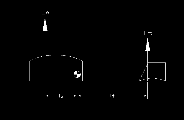
Lw = lift generated by
the
wing
Lt = lift generated by the
tail
lw = distance from the
balance
(pivot) point to the lift force of the wing
lt = distance from the
balance
(pivot) point to the lift force of the tail
For stable flight the
moment
(lift force times the distance) of the wing must equal the moment (lift
force times the distance) of the tail.
This can be expressed
mathematically
as: (Lw * lw) = (Lt * lt)
if (Lw * lw) is greater
than
(Lt * lt) then the nose of the model will pitch upwards.
if (Lw * lw) is lower than
(Lt *lt) then the nose of the model will pitch downwards.
So a stalling model is
an
indication that the nose up forces are winning the see-saw balance. So
to counteract that, we have several options.
-
Reduce the incidence
in the
wing. If you have plus 1/8" incidence, then reduce it to about 1/16" of
plus incidence, and fly again. However, do not ever reduce the
incidence
to a point where the incidence is negative in the wing, you always want
zero or positive incidence in the wing.
-
Move the balance point
of the
model forward. By changing the balance point, you are moving the pivot
point of the model to give the tail a longer lever in which to utilize.
You can move the balance point forward by adding clay to the nose,
moving
the landing gear forward, or you can remount the wing sockets further
back.
-
Check for and remove,
if necessary,
negative incidence from the tail. You may think that there is no
negative
incidence in the tail, but sometimes the balsawood warps, and it is
possible
for the tail boom to warp and bow upwards which is the same as raising
the trailing edge of the tail higher than the leading edge of the tail
(negative incidence). Please note that negative incidence in the tail
is
not necessarily a bad thing, it is only bad in excess. We built the
model
with zero tail incidence, but if the boom did warp upwards and the bow
is less than 1/8" then you should be OK. If it is more than 1/8" then
you
will have to either remount the tail boom with less incidence, or cut
the
leading edge of the stabilizer free from the boom and place a 1/16"
shim
between them and reglue it.
Diving is just the
opposite,
the forces are tending to point the nose downward. The correction for
diving
is basically the opposite as what you would do for stalling.
-
Increase the wing
incidence
to about 1/8" positive. You can either raise the front wingpost or
lower
the rear wingpost, or do a combination of both.
-
If you find that you
have more
than 1/8" positive incidence then you may want to add some negative
incidence
to the stabilizer. You can do this by cutting the trailing edge of the
stabilizer free from the boom and adding a 1/16" or even a 1/8" high
shim
to raise the trailing edge of the stabilizer upwards.
-
Move the balance point
more
aft. You can do this by moving the landing gear rearward, adding clay
to
the end of the tail boom, or by moving the wing forward. You can also scrape
off some of the weight off of the propellor.
These are the two basic
trim
problems to look for. The next thing we need to look for is how big is
the circle. The model should be flying in circles about 20 feet in
diameter.
If the circle is much larger or smaller then corrections should be
made.
First check to see if the model still has the tail tilt you built into
it. This diagram shows the possible types of tail tilt which are
possible
when viewing the model from the front.
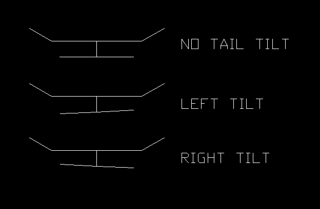
Your model should have
a
little bit of left tilt in the tail. If not then it needs to be
corrected.
A quick and easy method, which may seem extreme, is to grab the boom
about
2" behind the rear hook with your left thumb and forefinger, and then
grab
the boom about 1" further back with your right thumb and forefinger.
Then
twist your hands in opposite directions from each other making sure
that
the hand closest to the tail is twisting the direction you want to tail
to go. Be gentle when doing this, or you may over twist the boom and
crack
the wood. If you do not wish to use this method (I use it all of the
time
though) then you will need to remove the boom from the body and reglue
it. Be careful no to overdo the tail tilt otherwise it can cause other
flight problems. You should have a few degrees of tail tilt as shown in
the diagram above next to "LEFT TILT".
Turning problems can
also
be cause by insufficient left thrust or left rudder. Check to see if
the
model has one (1) to three (3) degrees
of
left thrust as well as the 1/8" of boom/rudder offset which was
built
into it.

Other trim problems can
come
into play at other parts of the flight. A typical flight can be broken
down into three segments. The first is the climb phase which is when
the
model climbs to the ceiling. Then as the rubber band winds down, then
you
enter the cruise phase which is when the model flies at about the same
altitude for several laps. Finally there is the descent, which is when
the model starts coming down from the ceiling and eventually lands on
the
floor.
Sometimes problems
occur
in one segment and not in the other which can be quite troublesome to
try
and figure out. A model may not circle at launch but then circles fine
20 seconds later, or it may try to dive at launch but then flies just
fine
moments later. Here are some frequent segment specific problems which
may
arise.
Model flies straight
during
launch:
-
Add more side thrust
to the
model
-
Add more left tail tilt
-
Check tail tilt at
launch, if
it looks like you have right tail tilt instead of left tail tilt then
you
may have a weak body which is twisting from the rubber band torque, and
will have to be replaced with stronger wood or wider wood.
-
Check to make sure the
body
is not bowing to the right during launch.
If
it is then the body is too weak and will need to be replaced, or made
from
wider wood.
Model dives during launch:
Model stalls during launch:
Left wing drops at launch
and
model does several fast low level laps then starts to climb:
-
This could be a
symptom of not
enough wing wash-in. Check to see if you have
1/8" wash-in, if necessary crack the spar by the wingpost and raise the
leading edge slightly until you have 1/8".
-
Too much left side
thrust in
the prop assembly. Check to see if you have 1 to 3 degrees of side
thrust
with the rubber band wound. If you have too much then reduce it a
little.
-
Too much rudder
offset. The
boom should be built with about 1/8" rudder offset. If you have more
than
this, then the rudder can overpower the model and cause it to dive.
Model shakes while it is
flying
around:
Model flies straight at
the
end of the flight:
-
This can be caused by
not enough
rudder offset in the boom. Add a little bit more rudder offset and see
if it helps out.
-
There is the
possibility that
the left wing (when looking at the model from the front) has wash-out
in
it. Wash-out is just the opposite of wash-in (which the right wing
should
have 1/8" of) and should not be present in the left wing or left
wingtip.
Wash-out is when the trailing edge is higher than the leading edge.
-
If all else fails,
place a small
piece of clay (about 0.3 grams) on the wingtip to help it turn.
Model stalls at the end of
the
flight:
-
Check to see if the
rubber is
bunching together by the rear hook. If this is happening then the
balance
point of the model is being moved backwards by the bunching of the
rubber.
To cure this, you will need to increase the height of the spacer
on the rear hook.
-
The other possibility
is an
aft balance point combined with downthrust in the prop. At the
beginning
of the flight the downthrust compensates for the aft balance point by
holding
the nose down down, and then towards the end of the flight the
downthrust
looses its effect and then the aft CG causes the model to start to
stall.
The cure for this is moving the balance point forward and removing the
downthrust.
The Zero-Zero trim
method:
The
last part of trimming I want to talk about is the zero-zero trim
method.
For maximum flight time, we want to have maximum lift with the least
amount
of drag possible. If you move the balance point (Center of gravity or
CG)
back, the efficiency of the model starts to increase. The reason being
that a further aft CG requires less incidence in the wing to fly. When
you truly reach zero-zero, the model has no incidence in the wing or
tail.
The point where the aerodynamic forces balance in this zero-zero
conditions
is called the neutral point. Typically we try to position the CG of the
model ahead of the neutral point to make the model stable. If the CG is
located behind the neutral point, then the model will become unstable
if
it is disturbed by any air turbulence. The distance the CG is
ahead
of the neutral point is called the stability margin. It is usually
expressed
in a percentage of the wing chord, so for the Olympus, the wing chord
is
4.70in (12cm) and the stability margin is 10% or 0.47in (1.2cm). This
means
that the 0.7" distance from the trailing edge of the wing (the balance
point) represents a 10% stability margin. The neutral point would then
be 0.70"-0.47"= .23" (5.84mm) in front of the trailing edge. So our
acceptable
balance point can really be anywhere between 0.23" and 0.70" in front
of
the trailing edge of the wing.
For a
zero-zero trim you want to be as close to the 0.23" position as
possible.
I would try about 0.30" and fly your model. You will notice that the
model
needs much less wing incidence, if it needs any incidence at all. The
other
thing you may notice is that the model takes more time to recover from
a dive than before. If your model hits a girder on the ceiling and the
nose dropped a little, it would correct itself in a few feet then keep
flying. With the zero-zero trim, the model may dive for ten feet or
more
before recovering. This is because the stability margin is so low, and
the 10% 'lever' which was 0.47" is now a much smaller 1.5% or 0.07", so
the time required to pull out from a dive is longer. So what is the
benefit?
Well the benefit is more flight time potential. The more optimal cg
position
can produce a 5 to 10% increase in flight time over a more stable CG
location.
But you have to weigh the benefits, if you fly in a small gym with lots
of obstructions, then a more stable CG may be better for you because a
ceiling bump does not loose much altitude. A higher ceiling may benefit
from the aft CG because the potential of hitting something is much
lower.
Back
to the main page.


